
How to create anaglyphs in MATLAB
13 August 2026
Despite technological advances in the field, anaglyphs have remained, for almost a century now, one of the quickest and most accessible ways of generating and viewing stereoscopic images. For this reason, they have a privileged place in classes on binocular perception, allowing some basic perceptual principles (e.g. binocular disparity, binocular rivalry, random-dot stereograms) to be illustrated with few resources.
In this context, a useful exercise for actively engaging students may involve creating their own anaglyphs from scratch. This tutorial provides detailed instructions for doing so using MATLAB – although there are freely available programmes for constructing anaglyphs, using MATLAB, which requires each of the necessary procedures to be specified step by step in the form of only four commands, provides greater clarity regarding the underlying logic and, consequently, the elementary principles underlying stereoscopy.
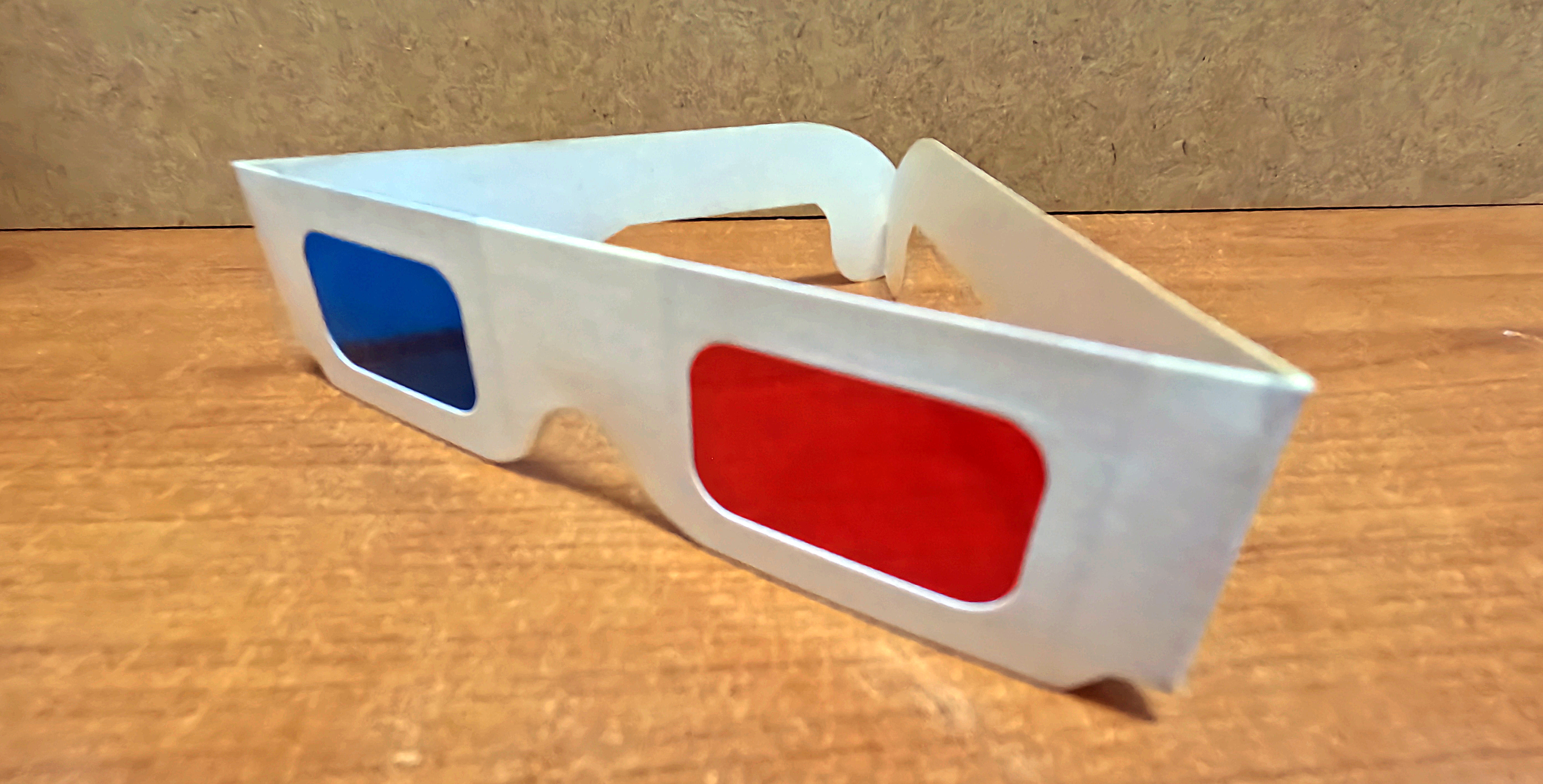
Of the various types of anaglyphs available (e.g. red-green, red-blue), we will focus on red-cyan anaglyphs – that is, the image presented to the left eye contains information only in the red RGB channel (and therefore requires a red filter in front of the left eye), while the image presented to the right eye contains information only in the green and blue RGB channels (= cyan; therefore requiring a cyan filter in front of the right eye). This choice is motivated not only by its particular suitability for anaglyphs displayed on screens, preserving some colour perception, but also because red-cyan glasses (see Figure 1) are widely available at affordable prices.
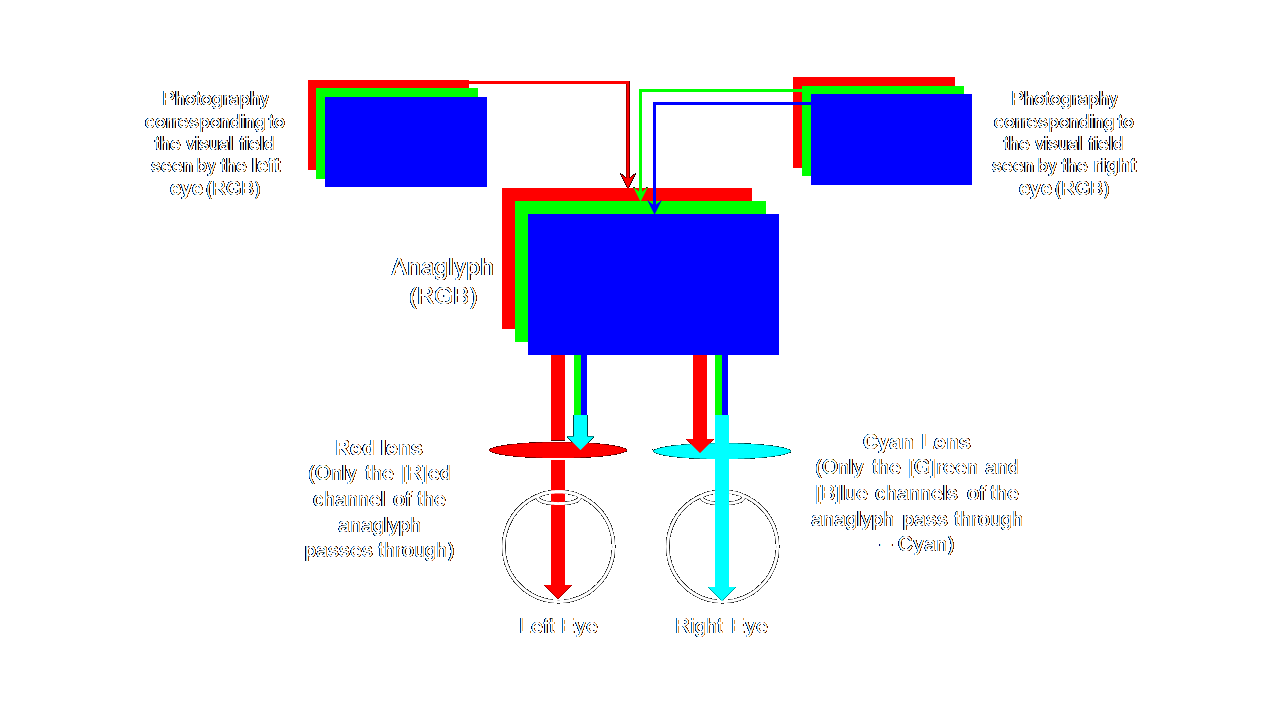
The basic logic underlying red-cyan anaglyphs can be seen in Figure 2. Two colour (RGB) photographs are combined into a single image – the information from the photograph to be viewed by the left eye is retained in the red channel; the information from the photograph to be viewed by the right eye is used for the green and blue channels, whose combination results in cyan. This composite image can then be viewed with red-cyan glasses, resulting in stereoscopic perception.
Naturally, for the instructions that follow, it is necessary to have two photographs taken in advance, from positions slightly offset horizontally from one another. These may have been prepared beforehand, or they can be obtained on the spot using the cameras on personal mobile phones. This is the most critical step in the whole process and can determine whether the anaglyph succeeds or fails. First, take one photograph – this will be the image presented to the left eye. Next, the mobile phone/camera should be moved slightly to the right, while keeping the distance from the photographed object and the height of the camera as constant as possible (the use of a tripod or, at the very least, a pile of books or even just a table is highly encouraged) – the amplitude of the movement to the right should be relatively small, no more than 4-5 cm (a smaller movement of just 1 or 2 cm is preferable to a larger one of 6 cm or more, even if the perspective appears to be exactly the same). Take a second photograph from this new position (the image for the right eye). Figure 3 shows an example of the two photographs required.
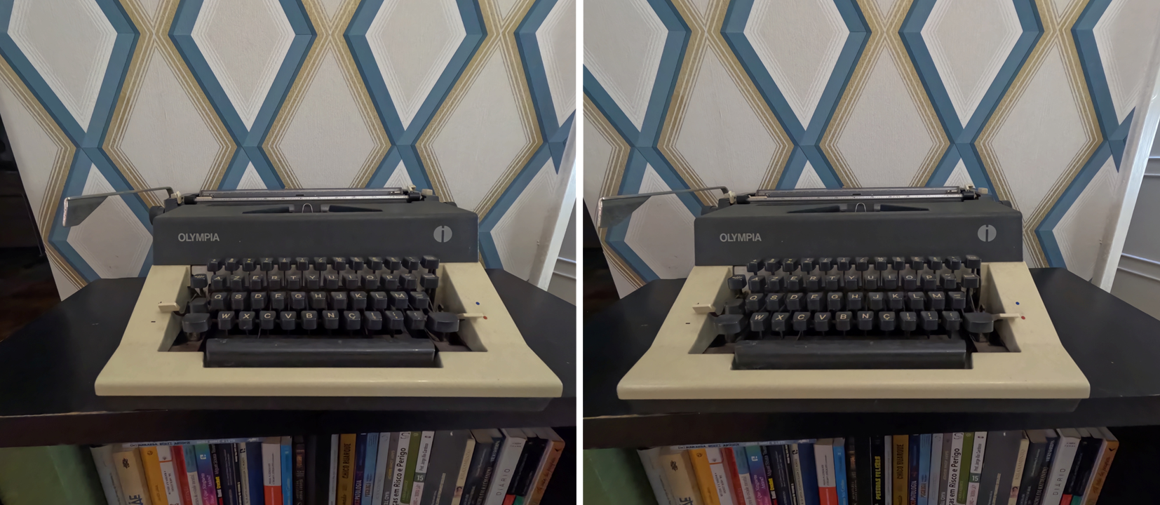
These two photographs should now be copied to the active MATLAB folder, and each of the following commands should be entered in turn (the comments accompanying each command explain exactly what is being done with it):
LeftEye = imread('IMGLeft.EXT'); % Import, as a matrix (named 'LeftEye'), the image to be shown to the left eye – replace 'IMGLeft' with the filename and 'EXT' with its extension
Anaglyph = imread('IMGRight.EXT'); % Import, as a matrix (named 'Anaglyph' – this will be used for the final anaglyph), the image to be shown to the right eye – replace 'IMGRight' with the filename and 'EXT' with its extension
Anaglyph(:,:,1) = LeftEye(:,:,1); % Replace, in the 'Anaglyph' matrix, the red channel (R) with the corresponding channel from the 'LeftEye' matrix
imshow(Anaglyph) % Display the final anaglyph as an image in a new window
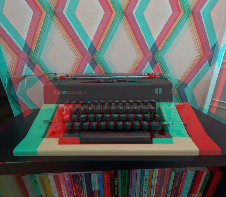
The result should be something similar to that shown in Figure 4 (in this case, the anaglyph is the one obtained from the photographs shown in Figure 3).